Rapid Prototyping Technology: Development, Applications & Future Trends
Concept Definition: Technological Leap from Prototyping to Rapid Manufacturing
Rapid Prototyping (RP) originated in the 1980s, with its core principle being the construction of three-dimensional solid objects based on the “layered superimposition” method. Its most distinctive feature is breaking free from the reliance on molds in traditional manufacturing, with the entire process driven by digital models. As an advanced direction of RP, Rapid Manufacturing (RM) differs in that it directly targets the production of end-use functional parts—such as small-batch customized interior components in the automotive industry and personalized implants in the medical field—rather than being limited to prototype verification. While their technical pathways are highly overlapping, there are fundamental differences in their application objectives. However, from the perspective of current industrial practice, RM still requires continuous optimization in terms of production efficiency (e.g., single-part manufacturing time), material performance (e.g., long-term aging resistance), and cost control (e.g., equipment depreciation allocation) in combination with specific industry scenarios.
Core Technology System: Characteristics and Evolution of Mainstream Processes
Currently, the three most mature RP technologies in industrial applications all follow the logic of “layered discretization + superimposed forming,” but they differ significantly in material compatibility and precision performance. Selection in practical applications should be based on specific scenarios:
Stereolithography Apparatus (SLA): Uses liquid photosensitive resin as raw material, which is cured point-by-point by ultraviolet laser. In practical applications, the industrial-grade ProX 800 equipment from 3D Systems can stably control precision within ±0.13mm (±0.005″) and achieve a surface roughness of Ra 2.0-3.5μm when manufacturing home appliance shell prototypes, making it suitable for scenarios requiring high appearance precision.
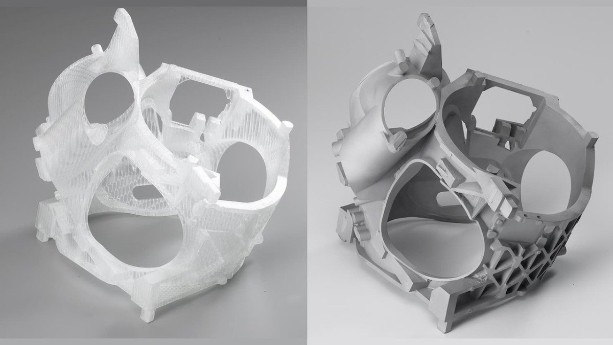
Selective Laser Sintering (SLS): Proposed by Professor C. R. Dechard from the University of Texas (USA) in 1989, it was initially used for nylon powder forming. The key advantage of this process is that unsintered powder can naturally support complex structures—for example, in the trial production of aerospace components, the EOS M 290 equipment can sinter Ti-6Al-4V powder to directly manufacture fuel nozzles with internal flow channels, without the need for additional support design, resulting in almost unlimited geometric freedom.
Fused Deposition Modeling (FDM): Forms parts by extruding filaments (e.g., ABS, PLA) through a heated nozzle, with relatively low equipment costs. Taking the commonly used prototype-grade Ultimaker S5 equipment as an example, when printing a 300mm×200mm×100mm plastic structural part, the tolerance is usually ±0.5% (with a lower limit of ±0.5mm), making it more suitable for manufacturing structural verification prototypes. Post-polishing is required for scenarios with high precision requirements.
In recent years, hybrid processes have gradually overcome the limitation of single-material use in traditional RP technologies. For instance, the FX10 printer from Markforged integrates Fused Filament Fabrication (FFF) and Metal FFF processes—it first prints a carbon fiber-reinforced plastic matrix via FFF, then embeds metal filaments, and finally processes the part through a three-step “printing-debinding-sintering” method. This enables the manufacturing of aerospace connectors (e.g., UAV landing gear brackets) that combine strength and lightweight properties. In applications at an aerospace supporting enterprise in Shenzhen, this type of equipment has realized the integrated manufacturing of small-batch (fewer than 50 pieces) components, reducing working hours by 40% compared to the traditional combined process of “plastic printing + metal processing.”